
A novel optical fiber transceiver offering 24 lanes at up to 10.3125 Gbps is presented; its external dimensions are 32.3 mm ×13.4 mm × 4.5 mm; it is compatible with the VITA66.4 standard or can be embedded on a host PCB; its operating temperature range is –40°C to 100°C.
Smiths Interconnect has developed compact 120G full duplex (12+12) 10.3125 Gbps/lane optical fiber transceivers for harsh environment applications such as Aerospace and Defense. These devices are designed to be embedded on printed circuit-boards in close proximity to high speed electronics in high performance embedded computing systems to optimize their performance. The same transceivers can also be integrated in board-edge connectors to free-up more space on the board and avoid optical fiber management. The active blind-mate optical connector interface associated to the board-edge mount application is based on the OpenVPX™ standards. These standards define interfaces between plug-in modules, backplane modules and chassis for products intended to be deployed in harsh environments.
These devices have been designed to maximize size, weight, and power (SWaP), being very compact, having a weight of 4.8 g and a power consumption around 120 mW/lane. Thermal management is optimized through multiple heat dissipation paths on the compact volume of these transceivers.
LightABLE optical transceivers
- Performance: 10.3125 Gbps/lane from −40°C to 100°C
- Sensitivity: better than -12dBm for BER10−12
- Configurations: 4TRX, 12TX, 12RX, or 12TRX
- Multimode OM3 fiber
- 850 nm wavelength
- Standard MT parallel fiber connector
- Embedded or board-edge mount (blind mate)
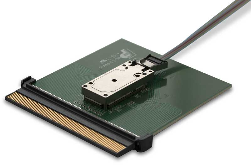
LightCONEX board-edge blind-mate optical interconnects
Define interfaces between plug-in modules and chassis for harsh environment applications.
Vita 66.4
Example of card layout for VITA 66.4.
The figure below shows the final configuration of the transceiver for both printed-circuit board embedded and board-edge mount application configurations. The embedded configuration is associated to Reflex's MicroClip™ technology that has proven its reliability in live vibration tests up to 41.7 grms and live fiber pull tests over 1 kg.
LightABLE LL used as a onboard embedded module.
Proprietary MicroClip™ MT ferrule
LightABLE being subjected to vibration test
LightABLE being subjected to live fiber pull test
LGA socket or connector
LightABLE LGA Interposers come in two sizes: 1 mm and 3 mm.
LightABLE LL with 1 mm and 3 mm LGA interposers.
Transceivers are secured with screws with 1 to 2 in.-oz torque values
(0.7 N-cm to 1.4 N-cm).
The board-edge mount configuration was made to be compatible with VITA 66.4 optical interconnect on VPX base standard with a drop-in adaptor. Both configurations are associated to LGA (land grid array) sockets. A technology that has proven to be the perfect compromise for the electrical interface to offer high-speed performance, height flexibility, screw-in mechanical reliability and practical insertion/removal capabilities. The LGA contacts have a pitch of 1 mm. Although heat dissipation through these pins is limited, the periphery of the LGA sockets does offer a good thermal path to the host board that can be designed to dissipate heat.
Technical drawing
The figure below shows the dimensions of these 12TRX transceivers compared with 4TRX transceivers, both including integrated microcontrollers. The height is comparable and the size (area or footprint) is about 1.5 times larger, for three times the communication capacity. Its weight is only about 25% larger than for the 4TRX. The optical interface for the 12TRX has a second row of optical fiber lanes on the same MT ferrule format. In order to make this design compatible with standard manufacturing technologies, we had to develop new optical alignment methods and rely on high precision automatic die bonding equipment.
Assembly
Main technical challenges: tolerance on components and assembly precision
Active alignement. Optical loopback with RSSI access through microcontroller
Passive alignment under trial (5 µm precision needed)
Thermal management
- 4 mounting screw holes are plated to help heat dissipation
- Donut shaped metalization in contact to screw heads connect to thermal relief immediate pads
- Thermal net dedicated, in-plane, inside the PCB help spread the heat.
- Thermal net connects to all mounting holes through thermal VIAS
- Worst case power consumption: 2.87 W at 85 °C case (~120 mW/lane)
- Free running without forced convection: ≤ 50 °C, without heatsink
- Thermal resistance: estimated at 14 °C/W
Test Setup
Power supply filtering: 3.2 V to 3.4 V, with π filtering circuit (low pass filter).
Evaluation board
Performance at 10.3125 Gbps/lane
With all lanes active: worst case
RX: −10 dBm sensitivity at 10-12 BER. To be optimized
Impact of cross-talk
TX eye with all lanes active
TX eye with no other lanes active
Results
The performances of the 12TRX transceivers are as follows: sensitivity per lane better than -10 dBm for a BER of 10−12 from −40°C to 85°C with all lanes active.
We are currently improving on the settings and build to operate up to 100 ºC and maintain −12 dBm sensitivity across all lanes. We believe this design offers the best “performance/ cost per lane” ratio in the industry, for the same proven rugged constructions associated to Reflex 4TRX products, that have been used for many years in harsh environment applications.
The environmental qualification effort that is planned for this new product includes:
- 1000 thermal cycling form −40°C to 100°C as per MIL-STD-883 method 1010
- Vibration tests as per MIL-STD-883 method 2007
- Live vibration tests as per MIL-STD-1344 method 2005
- Mechanical shock tests as per MIL-STD-883 method 2002 and MIL-STD-1344 method 2004
- Thermal shock tests as per MIL-STD-883 method 1011
- Damp heat tests as per MIL-STD-202 method 103
- Salt fog as per MIL-STD-1344 method 1001
- Sand & dust as per MIL-STD-810 method 510
- Insertion/extraction force as per MIL-STD-1344 method 2013
- 500 mate/unmate cycles as per MIL-M-28787.
Operating temperature range (case)
- Operation at −40 °C: TX coupling loss (~2dB) due to alignment precision vs CTE; RX sensitivity−10dBm
- Operation at room temperature: TX Pavg: 1dBm, ER: 6dB; RX sensitivity −10dBm
- Operation at 85°C: TX Pavg: 0dBm, ER: 9dB; RX sensitivity −10dBm
- Operation at 100°C: Thermal shutdown to be compensated by less demanding settings
- Results with same default settings for the whole temperature range / potential of optimization through the microcontroller
DVT to be completed
Conclusion
- Introduction of a new 12TRX up to 10.3125 Gbps/lane rugged optical fiber transceiver
- Best “performance / cost per lane” ratio in the industry, for rugged transceiver technology
- Performance optimization to be completed by minor design/assembly adjustments
References
- M. Têtu, “Rugged Optic Interconnects Open New Possibilities for HPEC Systems in Harsh Environment”, RTC Magazine, February 2016, pp. 40-41.
- W. Wong, “Optical Goes Small and Rugged”, Electronic Design, Feb. 6, 2017. Available here
- G. Rocco, “OpenVPX™ Tutorial and Common Practices”, MIT Lincoln Laboratory, Updated January 15, 2018. Available here.
- J. Lauzon, T. Oleszczak, D. Rolston, R. Varano, S. El Kharraz, N. Safdari, “Reliability of Connectorized 10Gbps/channel Optical Fiber Transceivers”, IEEE Photonics Society AVFOP conference, November 2016, ThA1.3.
- Optical Interconnect on VPX – Base Standard, ANSI/VITA 66.0-2016, July 1, 2016.