Infrastructure for Ultrafast CCS (Combined Charging System) particularly in highway services and major forecourts within cities is pivotal for continued adoption of battery electric vehicles.
To assist with the generational change in how we all drive, various innovative solutions are being introduced with charging technology. One of such is rated boost current, which involves short-term currents exceeding the rated continuous current[1]. The boost current mode allows to reduce charging times, a goal the industry has been working towards to bring parity in how users experience while refuelling internal combustion engines.

However, there is one common weakness with all ultrafast CCS technology- power loss, which happens due to Joules heating of DC+ and DC- sockets. While power loss may seem innocuous given its prevalence in the industry, but if not addressed it can be the one of the major reasons for the vicissitudes in adoption of BEV, as drivers will continue to experience the gap between the time it takes charging versus refuelling a car with internal combustion engine.
Chargers with rated boost current, is the answer to drive that behavioural change resulting in win-win situation for both the CPOs (Charge Point Operators) and the users of BEV (Battery Electric Vehicles).
The Challenge
The contact technology used for DC+ and DC- sockets within the CCS plugs for ultrafast charging are machined. These contacts while charging, is in contact with machined pins in the BEV. It is well established that surface finishes of these contacts are not smooth but comprises of many asperities. These spots, termed as a-spots, provide the only conducting paths for the transfer of electric current and as seen in Figure 1 they are smaller than the full length of the contacts.
Since the conducting paths are constricted through the a-spots, the electrical resistance increases, and this increase is termed as the constriction resistance. Further, contaminant films on the mating surfaces increase the resistance of a-spots. The total resistance due to constriction and contaminant films is termed the contact resistance.
The constriction current produces Joules heating and increase in local temperature, which further exacerbate with thousands of mating cycles. The higher the electrical contact resistance, the higher the level of contact overheating and therefore unwanted Power Loss.
The Solution
The Hypertac Green ConnectTM sockets designed to IEC2196 and SAE J1772 standards can deliver up to 90% more energy at 500A boost current mode. This represents a significant improvement over conventional technologies, allowing faster, more efficient charging with less energy loss.
Designed for ultrafast high-power charging, the Hypertac Green ConnectTM excels in boost current mode, providing longer period where current exceeds the rated continuous current. The contact is built to endure up to 60,000 mating cycles — a lifespan far exceeding most alternatives in the market — ensuring that charge point operators (CPOs) can rely on the same connector for extended periods without incurring additional service cost and performance degradation.
At the heart of technology as seen in seen in Figure 2, the Hypertac Green ConnectTM is Lead-free and Beryllium free hyperboloid contact. The body of the Hypertac Green ConnectTM made from high conductivity copper alloy (approximately 90% IACS or International Annealed Copper Standard) will deliver superior conductivity performance compared to other CCS DC+ and DC- sockets which are manufactured with brass (approximately 25% IACS). Further, unlike other socket technologies which are stamped to a hyperboloid geometry with high electrical contact resistance, the Hypertac Green ConnectTM socket has wires in the hyperboloid cage made from high conductivity novel material (approximately 55% IACS).

The Tests
Hypertac Green ConnectTM alongside sockets offered by two other leading manufacturers of ultrafast CCS plug was tested. Mating cycle test - Firstly, a test bench was set up, where the pin and socket pairs were mated and unmated up to 60,000 cycles keeping all other variables same. At the end of 100, 500, 1000, 2000, 5000, 10,000, 15,000, 20,000 and then increments of 10,000 cycles the machine was stopped to carry out certain critical measurements – namely Contact resistance, temperature rise, and energy transmitted at 500A.
After 15,000 cycles, tests with two other leading manufacturers α and β of ultrafast CCS plug’s sockets were stopped as the plating worn out exposing the base copper material, tests on Hypertac Green ConnectTM however carried out up to 60,000 cycles. Contact resistance test – The test set up involved applying 100 Amps through the contacts and then measuring the voltage drop across the pin and sockets. The objective of this test was to observe the behaviour of the contact resistance across the product’s lifecycle between 0 up to 60,000 cycles. Table 1 shows the % increase of the contact resistance for the period defined by the IEC standard.
|
Manufacturer |
% increase in Contact resistance from 0 to 10,000 mating cycles |
|
Hypertac Green ConnectTM |
33% |
|
Manufacturer α |
67% |
|
Manufacturer β |
53% |
Table 1 - % increase in Contact resistance between 0 to 60,000 mating cycles
Results of the full test as evident in Figure 3 demonstrate Hypertac Green ConnectTM has low and stable contact resistance performance, while the contacts from the two other leading manufacturers showed steep increase in the contact resistance performance.
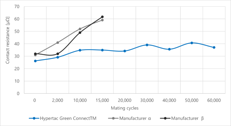
Figure 3 - Contact resistance between 0 to 60,000 mating cycles
Temperature rise test - In this test, 1.5m of 70 sq mm cable was terminated on each of the contacts and 250A was applied through each of them. This current was applied until the samples under tests reached thermal stability. Temperature rise was then measured through the difference between the temperature reached by the contacts and the ambient temperature. The objective of this test was to observe the temperature rise and whether it exceeded the critical temperature required for derating.
Results as shown in Figure 4 demonstrate the Hypertac Green ConnectTM has the lowest temperature rise due to the lowest contact resistance (as evident in Figure 3).
Ability to keep low contact resistance and low temperature is possible through high number of contact points with the wires of the hyperboloid cage and the high conductivity of the new wire material. In addition, the development of an additional feature within crimp termination allowed further to lower the heat generated in the connection between the cable and the socket.
This results demonstrate, Hypertac Green ConnectTM can carry more current without the need to increase the size of cable. The temperature rise for the two other leading manufacturers of ultrafast CCS plug’s sockets was close to +50°C from ambient temperature of 23°C after 10,000 cycles, whereas the temperature rise for Hypertac Green ConnectTM was around +32°C.
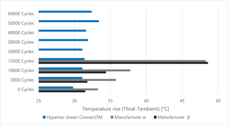
Figure 4 - Temperature rise at 250A between 0 to 60,000 mating cycles
Boost current mode test - In this test set up, 500A of boost current was applied on the samples under test through 1.5m of 70 sq mm cable and time was measured for +50°C temperature rise. The objective of this test was to understand how long (boost duration) and therefore how much energy (kWh) could be transmitted within the +50°C temperature rise.
Given the low contact resistance and temperature rise as demonstrated in Figure 3 and Figure 4, it was no surprise, that the Hypertac Green ConnectTM was able to carry boost current 500A for a longer time than the two other leading manufacturers, as evident in Figure 5.
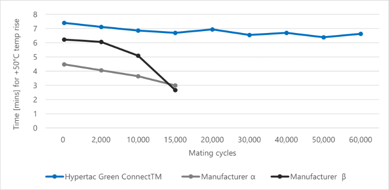
Figure 5 - Energy transmitted at 500A between 0 to 60,000 cycles
Assuming 1000V of operating voltage and using the following formula, the energy transmitted (Wh) was calculated = Voltage (V) * Current (I) * Time (h). Figure 6, demonstrate that Hypertac Green ConnectTM can transfer up to 90% more energy transferred at 500A boost current mode.
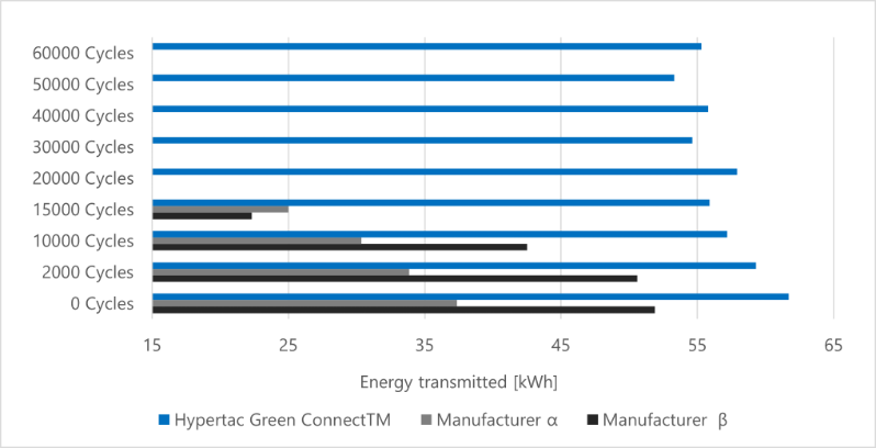
Figure 6 - Energy transmitted at 500A between 0 to 60,000 cycles
Conclusion
 The goal to reduce charging time is shared by all in the industry. However, to realise that goal, using the same technology for boost current mode would fail.
After conducting all the tests, the results support that the Hypertac Green ConnectTM can deliver superior mechanical durability, electrical performance and longer boost duration. The Hypertac Green ConnectTM demonstrated limited wear of the plating with no exposure of the base copper alloy even after 60,000 cycles, low contact and temperature rise, resulting in extended duration for boost current which ultimately delivered up to 90% more energy at 500A boost current mode.
Smiths Interconnect’s Hypertac Green ConnectTM is the solution that the industry waited with bated breath. The technology delivers significant improvement over conventional connector technologies, allowing reduction in charging time, more efficient charging with less energy loss, shorter cooling down duration, all of which collectively will help CPOs with higher revenue and greater intervals for replacing contacts as spares.
References
[1] White paper of Charging Interface Initiative e.V. – Introduction of boost current for EV DC-Charging 2025-02-04
[2] Holm, R., Electrical Contacts, Springer