Skip to content

Micro Quadrax/Twinax

NDL, SMA and Micro-D Size Shells

Micro quadrax/twinax connectors are available in threaded, quick disconnect, SMA and Micro-D size packages, 25% smaller in diameter than SMA coaxial connectors, controlled impedance with tightly spaced PCB footprint.

Download Brochure

Features & Benefits

  • Micro twinax available in threaded, quick disconnect, SMA and Micro-D size packages
  • 25% smaller in diameter than SMA coaxial connectors
  • Controlled impedance with tightly spaced PCB footprint spacing
  • Cable assembly options available
  • Featuring Sabritec technology

Overview

Micro quadrax connectors maintain the signal to shield impedance throughout the mated connector pair (quad configuration applications exceeding 1 Gbit/sec) and are available in threaded versions including straight and right angle cable mount and PCB mount configurations. Micro Twinax line features matched impedance miniaturized connectors that provide the user with controlled impedance and tightly spaced PCB footprint spacing. These connectors are available in true differential twinax packages of NDL, SMA and Micro-D size shells. The NDL Micro Twinax Series is offered in threaded and quick disconnect styles and are 25% smaller in diameter than SMA coaxial connectors. The quick disconnect version has a diameter of .250" max and the threaded version has .250" Hex coupling nut.

Related Products

  • Image of Micro-D Twinax (MDTX)

    Micro-D Twinax (MDTX)

    Twinax blindmate assemblies fitted into a low-profile metalized Micro-D style shell.

Related News

  • Image of Space Missions

    Expanding the Frontier

    As Space Missions evolve, so do Smiths Interconnect’s light and compact connectivity solutions.

  • Image of LightCONEX_43

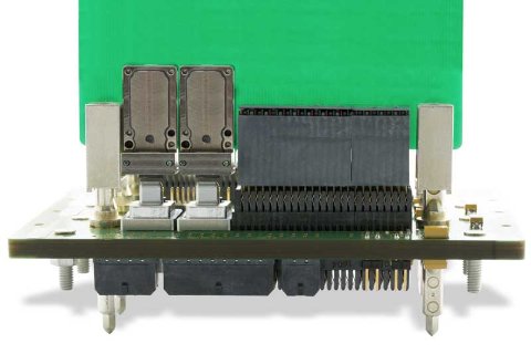
    Overcome Challenges in Embedded Optical Interconnects Design

    The above article has outlined the advantages and challenges of using fiber optical interconnects. To use fiber optic cables, the electrical signals need to be converted to light signals using fiber optic transceivers. While there are many challenges to embedded fiber optics design, the benefits are substantial. The guidelines and design check list provided will help developers select the best solutions for their needs.

  • Image of BGA electrical interface

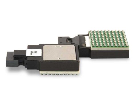
    Understanding the Test Criteria of Optical Fiber Transceivers Used in Space

    In space, high performance components must be able to deliver reliably in the punishing environment. It is optical transceivers that drive transmissions, converting signals to and from a copper-resident format. Fiber optics communications provide high bandwidth and low latency signaling. Signal transmissions through fiber optic cables (FOCs) provide immunity to EM/RFI interference, crosstalk, and voltage level surges. Fiber optics’ accuracy and reliability exceeds traditional cabling. Covering 1,000 feet requires four pounds of FOC versus 39 pounds of copper wiring, and fiber optics also consume less energy than copper. To convert electrical signals from circuitries with copper output to fiber optics, optical fiber transceivers are usually required.

  • Image of SpaceNXT™ Aurora Hard Metric Backplane connectors

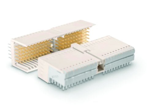
    SpaceNXT™ Aurora Hard Metric Backplane connectors

    Smiths Interconnect’s SpaceNXT™ Aurora Hard Metric Backplane connectors for the next generation of satellites applications Products pre-tested and qualified help maintain consistent signal in mission-critical environments.