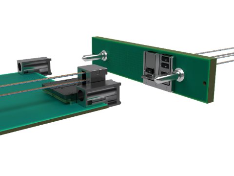
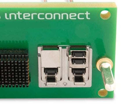
The low-profile plug-in module connector is screwed on the board edge through an interposer, saving board space and eliminating fiber cable handling. The backplane connector has a spring-loaded mechanical transfer (MT) ferrule to ensure a secure optical mating connection under extreme shock and vibration conditions.
- Increases volumetric density of 3U and 6U high-speed switch and payload OpenVPX boards by integrating optical transceiver into plug-in connector.
- Intermateability with VITA 66.5-defined backplane connectors enables multiple sources and drives faster design cycles.
- Reduces optical interconnect SWaP with rugged MIL-STD qualified, edge-mounted, optical interconnects.
- Enables ultra-high port bandwidth density of up to 720 Gbps full-duplex in a half-width slot.
- Simplifies OpenVPX board assembly and rework by eliminating fiber pigtail on edge-mount transceiver.
- 10G and 28G per channel datarates in TRX, TX-only, and RX-only configurations.
Applications
- OpenVPX single board computing
- C5ISR embedded systems
- AESA radars
- High throughput Ethernet switches
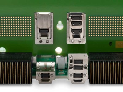
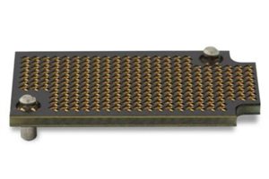
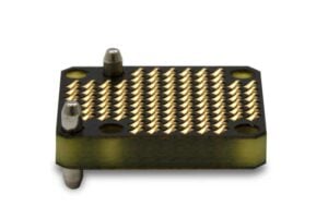
LightCONEX backplane module connectors (style C and D shown here side-by-side).
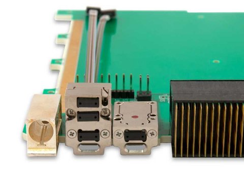
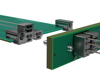
LightCONEX plug-in module connectors (style D and C shown here side-by-side).
The LightCONEX® plug-in module connector contains the optical transceiver with its MT ferrule, an LGA interposer, and a connector shroud.
- Plug-in module connectors are secured with screws directly to the edge of the host board along with their dedicated LGA interposers.
- 5.6 mm transceiver height (module and interposer)
- Up to two additional passive optical ports that are connected with detachable cables to mid-board mounted LightABLE transceivers.
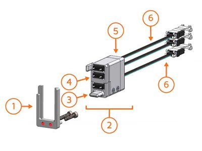
The main components of the optical plug-in module connector are:
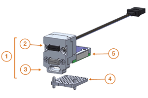
- Connector shroud, with:
- Optional additional MT ferrule(s) in positions MT-B and MT-C or 10 nanoRF
- Slot Primary Guiding Feature
- Interposer
- Optical transceiver (its MT ferrule in position MT-A). Plug-in connectors do not include cables. Cables are ordered separately.
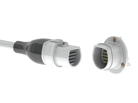
Optical transceiver with connector shroud
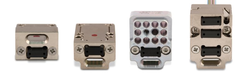
Style A
The LightCONEX plug-in module connector Style A is dedicated for the VITA 66.4 aperture and is a unique style with the slot primary alignment feature located above the optical transceiver.
Style C and D
The LightCONEX plug-in module connector for the VITA 67.3 apertures are available in two versions. They have connector shrouds for each respective styles with the slot primary guiding feature located below the optical transceiver.
- Style C
Style C has one optical transceiver only. Style C Hybrid has one optical transceiver with 10 nanoRF above - Style D
Style D has one optical transceiver and two cabled MT.
Interposers
 |
 |
| 28G 4TRX optical module, Style D | 96-position interposer |
LightCONEX plug-in module connector options:
Optical transceivers
The plug-in module connectors are equipped with optical transceivers offering multiple transmit and receive and bandwidth configurations :
- LightCONEX 10G 4TRX module: for Styles A, C, and D
- LightCONEX 10G 12RX, 12TX, and 12TRX modules: for Styles A, C, and D
- LightCONEX 28G 4TRX, 12TX, and 12RX modules: for Style C and D
Interposers
- 415-00005: 2.74 mm, 96 positions. Style A
- 415-00011: 3.03 mm, 233 positions. Style A
- 415-00018: 1 mm, 96 positions. Style C and D
- 415-00019: 1.2 mm, 233 positions. Style C and D
- 415-00041: 1.55 mm, 96 positions. Style C and D
LightCONEX optical performance
The LightCONEX 10G LC Series and LightCONEX 28G LC Series optical modules are available in different configurations. These modules offer flexibility, light weight, very high bandwidth, and forward compatibility.
 |
 |
| 10G 4TRX optical module, Style C | 28G 4TRX optical module, Style D |
LightCONEX 10G 4TRX, 12RX, 12TX, and 12TRX modules
- Performance: 10.3125 Gbps/channel from –40 ºC to 85 ºC
- Size: 5.6 mm high (module and interposer)
- Ruggedness: MIL-STD 883 shock and vibration qualified
- Ingress protection: Moisture and thermal shock resistant
- Reach: up to 100 m, OM3 fiber
- Sensitivity: –12 dBm or –9 dBm with BER 10–12
- Power consumption: 1.4 W (12-channel, 10.3125G). 2.8 W (24-channel, 10.3125G)
LightCONEX 28G 4TRX modules
- Performance: 28 Gbps/lane from –40 ºC to 85 ºC
- Size: 5.6 mm high (module and interposer)
- Ruggedness: MIL-STD 883 shock and vibration qualified
- Ingress protection: Moisture and thermal shock resistant
- Reach: up to 70 m with OM3 fiber and 100m with OM4
- Sensitivity: –7.5 dBm (typical) with BER 10–12
- Power consumption: 1.4 W (4+4-lane, 28G)
The LightCONEX® optical backplane module connector consists of a connector shell and insert. The shell is designed to provide float for the insert in both the X- and Y-directions to enable alignment of the MT ferrule mating interfaces. The design complies with the ANSI/VITA 66.4 mating requirements with the MT ferrule displacement occurring within the backplane connector.
The main components of the backplane module connector are:
- Connector shells for VITA 67.3 Module Types C, D, and F.
- Connector inserts available in VITA 66.5 Styles A, C, and D. The main components of the insert are:
- Tab primary guiding feature
- MT ferrule(s) with alignment pins
- Removable fiber back-clamp
- Optical cable assembly with spring (several cable options are available).
Connector shells
Different backplane connector shells are available to accommodate VITA apertures:
Backplane connector shells for:
- Module Type F
- Module Type D
- Module Type C
- Module Type E
Connector inserts
The LightCONEX backplane connector inserts are available in three styles:

Fiber Optical Transceiver for military and aerospace applications