

The potential for interference between the telecom 5G C-band (3.7 to 3.98 GHz) and radio altimeters (4.2 to 4.4 GHz) frequencies is a growing concern in the aviation industry. The FCC and the FAA are addressing this concern with the radar altimeter interference by reducing the 5G transmission power around airports and limiting the 5G networks within about 2 nautical miles of runways at US airports.
Alternative Filter Solution:
An alternative solution is presented that applies RF filtering of the 5G frequencies within the receiver of the radar altimeter. This filtering will suppress or attenuate the 5G signals from interfering with the radar altimeter system.
To be concise, consider the solution of implementing a filter in the radar altimeter. As stated above, these systems operate in the 4.2 to 4.4 GHz band and are used to provide precise altitude to aircrafts. An RF filter placed within the radar receiver that significantly rejects the 5G C-band frequencies would mitigate the occurrences of system malfunction or erroneous altitude information. Furthermore, the additional loss of the filter must be kept minimal to maintain the performance and sensitivity of the radar altimeter. Finally, the filter should be designed to provide a robust, but cost-effective solution for the radar altimeter system.
Smiths Interconnect has developed a Combline Cavity Filter solution to address this requirement. This filter solution provides rejection of more than 55 dBc in the 5G band, while also providing an insertion loss of 0.7 dB maximum in the radar altimeter band. This effectively attenuates the potential interference within the radar altimeter to ensure proper functionality.
The passband of this filter is shown in Figure 1
Figure 1: Combline Cavity Filter Response
The filter’s electrical response has the specifications listed in Table 1. A typical cavity design to meet these specifications would have seven sections with each section having adjustable screws to enable a technician to tune the filter into the required final specifications. This is effective, but it increases the amount of labor required for each filter. Smiths Interconnect has designed a solution that greatly reduces the amount of tuning screws to significantly reduce the cost of the filter. This design will enable to provide a solution that meets the required specification and also be cost effective for the market.
Table 1: Cavity Filter Specifications
| Specification | Min | Typical | Max | Units |
| Center Frequency | 4300 | MHz | ||
| 3 dB Bandwidth | 280 | MHz | ||
| Insertion Loss (4200 to 4400 MHz) | 0.4 | 0.7 | dB | |
| Return Loss | 14 | dB | ||
| Stopband Attenuation 4000 MHz | 55 | 60 | dBc | |
| Stopband Attenuation 4600 MHz | 58 | 60 |
dBc
|
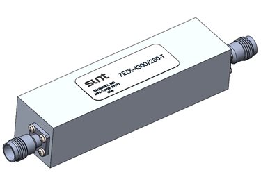
The compact filter solution size is 4.19”L x 0.98”W x 1.1”H for the length, width and height and will provide the market with a very efficient method of eliminating the interference between 5G frequencies and the radar altimeters on aircrafts. The filter solution is compliant to the conditions outlined in DO-160G, Environmental Conditions and Test Procedures for Airborne Equipment. The outline of this filter is shown below in Figure 2.
Smiths Interconnect is excited to support solutions to alleviate issues with the RF and Microwave products. Our RF Filter Select Plus Tool can assist with filter selection and topologies. As the RF communication spectrum continues to increase, Smiths will continue to provide solutions that meet the market demand. Our RF Filters have been supporting the demand of our customers for over 35 years and we will continue to innovate our products to support this demand now and in the future.