

Isolators and circulators are routinely used in communications and radar applications including AESA antenna, SSPAs and signal processing equipments and are generally available as Coaxial, Waveguide, stripline or microstrip types.


Circulator Device Schematic Isolator Device Schematic
Coaxial isolators (and circulators) are the most common type of ferrite device available and produced by many companies. In its simplest form a coaxial ferrite isolator offers reasonable performance, readily reproducible and importantly very easy to use. You’d be right to ask that given this ubiquity and simplicity “what is it that Smiths Interconnect coaxial devices offer that can’t be found elsewhere”?
Users expect electrical performance that is stable over temperature and appropriately packaged so that the system is electrically stable, mechanically robust and reliable within the intended application and environment. Smiths Interconnect isolators and circulators are designed and qualified to meet these expectations and comprise many features designed to meet these expectations as the following example illustrates.
Physically Smiths Interconnect’s isolators are like no other available. Most noticeable are the RF interconnects which are compliant with MIL-DTL-39012 but are integrally machined into the device housing; in other words, the housing and connectors form a monocoque structure that is not only incredibly robust, but also allows the devices to be mechanically compact. We refer to these as solid connectors.
The device housing is made of a grade of Stainless Steel that optimizes and internalizes the magnetic field, reducing the radiated fields and eliminating the need for shielding plates. Typically, our devices are magnetically shielded to ~ 0.0005Am^2 in X-Ku-Band. If you could see behind the an SMA connectors’ PTFE insert the internal structure is arranged so that the PFTA dielectric minimised making the dielectric that or air which allows the connector to function well above the frequency that SMA connectors normally operate , while maintaining exceptionally low insertion loss. For example, our 22-25GHz SMA isolator has an insertion loss of 0.25dB over temperature which is a similar performance to our 7.0-10.5GHz isolator.
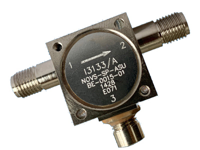
S-Band low power isolator featuring 2 extended barrel SMA (f) “solid” connectors
A “solid” state connector is produced in-house, which saves costs, delivery time and reducesrisk. Most importantly however it means the mechanical housing can be smaller, as it no longer must be dimensioned to accommodate the connector flange and the screws used to secure it. Our solid TNC connectors boast the same advantages as the solid SMA types and tend to be used where the RF power is too high for an SMA. Recently we successfully qualified an L-Band TNC circulator to 1.5kWpk and 225W average under full reflection (any phase) conditions (equivalent to 6.0kWpk and at least 450W of average power).
High-power stainless-steel isolator housing used in L & S -Bands featuring TNC (M) and TNC(f) “solid” connectors
Because the housings are machined to very tight tolerances, our users can mount our devices on either of two faces thus ensuring the connector center contact is on the device center line. This is why our isolators tend to include a label on each side: if the isolator has two SMA (f) connectors it can be used as a clockwise (CW) and counterclockwise (CCW) device with the label prominently displayed and without requiring to be shimmed.
The internal structure (junction) is under rotational compression. This makes the device essentially immune to the effects of mechanical vibration and shock. This is not a new approach and has been used for over 40 years. What is new however is that the combination of the threaded lid and internal, patented grounding gasket virtually eliminates two of the contributions to the insertion loss.
Another feature is that there are no seams or joints, which means that our “solid” connectors are RF sealed “by design” and there is no need for conductive epoxy. In recent tests Smiths Interconnect’s facility in Dundee, Scotland used our in-house reverberation chambers to demonstrate a shielding of more of 85dBi on SMA connectors at L to K-Band. We do not need to use any epoxies to RF seal the structure, but as a precaution we treat the threaded lid using conductive epoxy to minimize the radiated electromagnetic fields.
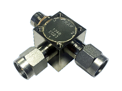
K-Band low power isolator featuring barrel SMA (m) “solid” connectors
Are you wondering how we attach the center contacts to the center conductor? As it is impractical to solder the piece parts externally and pass the assembly into the cavity, we use a contactless induction soldering and inspect the resultant solder joints using our in-house 3D x-ray machine, whose 160keV beam makes short work of up to 5mm of steel.
Most isolators are produced by terminating one of the ports depending on the users’ mechanical preferences. The terminations tend to be 50 Ohm rod resistors whose mechanical and electrical properties make them ideal for producing superbly well-matched impedances and ensuring excellent isolation that is repeatable and temperature stable.
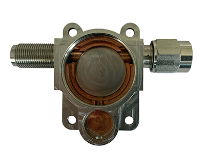
A typical isolator construction is illustrated in the following simplified diagram.
Potential customers interested in knowing more about this and related capabilities may contact Smiths Interconnect to discuss their specific needs. Our experienced technical staff will be pleased to detail the potential performances, mechanical details, and share the fruits of Smiths Interconnect’s 40 years of experience designing and producing coaxial isolators and circulators.