
The equipment required to simulate the rigors of launch and operational use in deep space, however, requires significant investment in facilities and highly skilled labor that most companies do not have. Companies may either have to rely on external test services, adding to costs, extending development and delivery schedules; or attempt to negotiate away certain critical test needs.
Many certification organizations and government agencies require impartial third-party laboratories to perform these tests for integrity assurance. Smiths Interconnect, a global supplier of cutting-edge connectivity solutions, has invested in a comprehensive range of environmental tests at their Dundee facility. This offers the important capability to customers not prepared to negotiate on fundamental reliability and insist on demonstrable compliance.
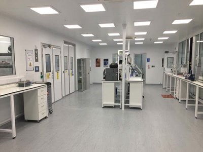
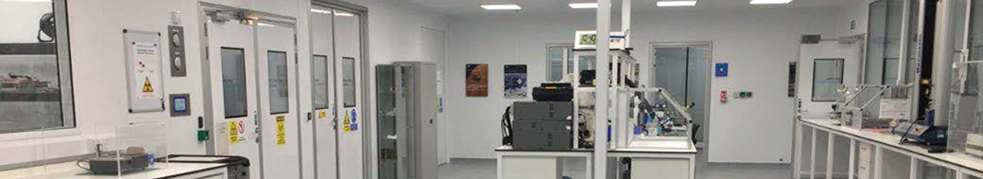
Dundee site qualification and test laboratory general purpose test area.
Types of environmental tests
Critical flight hardware malfunctioning when exposed to severe environmental conditions can lead to system degradation and catastrophic mission failure. For unmanned missions, this is unfortunate and expensive; however with the expected increase in manned space exploration, this could result in human tragedy. Once launched, it is usually impractical to repair or replace flight hardware, so several layers of redundancy must be added to mitigate such failure. This increases costs, reduces overload payload capacity and is not always possible. In this case, any single-point failure area is subject to additional scrutiny to identify potential design flaws or limitations. These tests cannot be used for every part and are thus reserved for a sample set, with the remainder of the manufactured lot exposed to reduced levels of similar tests still stringent enough to screen for failures and risk.
Launch vibro-acoustics
During initial ascent, the launch vehicle engines develop high-level acoustic noise and vibrations. In fact, acoustic levels during launch of the space shuttle approached almost 200 decibels, which could produce pressure waves that could flatten structures in the launch pad’s immediate vicinity. When the launch vehicle reaches a certain point, aerodynamic loads develop high acoustic levels on the payload fairing that can generate dynamic pressure loads in excess of 4 psi. These can excite launch vehicle vibrations damaging to flight hardware. For this reason, products or systems are tested at Smiths’ Dundee Test and Qualification laboratory by mounting the flight hardware onto electrodynamic shakers that apply high-level vibrations over a wide spectrum in all three axes.
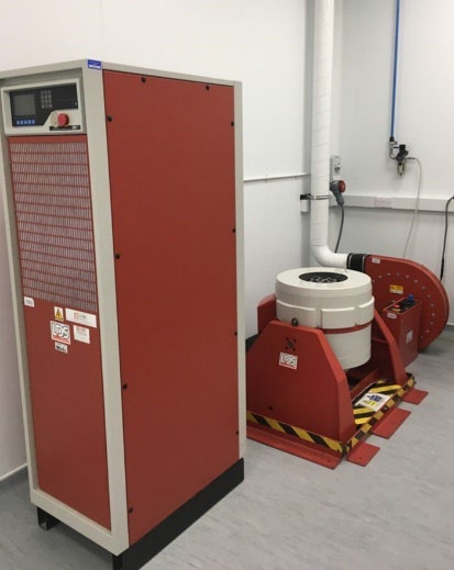
Figure 2. Electrodynamic shaker system.
Shock and deployment loads
During initial stages of ascent, ejecting the launch vehicle and payload boost stages is accomplished using explosive devices to shear bolts and allow springs to propel the expended stage safely away from the payload. Once the payload is on-orbit, pyrotechnic charges deploy antennas, solar panels and other appendages. Each time a pyrotechnic device is used, it produces severe short duration impulses or shocks, which can damage sensitive instruments, optics and electronics. Pyrotechnic shocks are simulated with shakers and shock impulse tables programmed to simulate precise shock response spectra (SRS). This involves fixing the unit to a table and impacting the table with a massive hammer-like object. The shock waves are transmitted to the product; slow-motion imagery occasionally observes the effects as the energy is absorbed and dissipated.
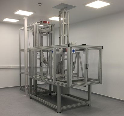
Figure 3. SRS mechanical shock test system.
Thermal and vacuum loads
When a space payload is in orbit around the earth, it passes from direct sunlight to darkness in a precise and calculable period. Depending on the orbit, this could range from once per day to every 90 minutes. In the vacuum of space, the lack of atmosphere prevents temperature control through natural convective heating and cooling. As a result, temperature loads can be extreme, cycling over a wide range from -160° C to +120° C, causing differential thermal strain and outgassing of electronic components, connectors and other materials. Outgassing can result in a local conducted “atmosphere” aboard a spacecraft and, unless avoided or passed into space, can cause a unique set of issues.
Thermal and vacuum loads are simulated using specially designed chambers (Figure 4) that subject the hardware to mission-appropriate thermal and vacuum. In some tests, the product can even be subjected to bursts of radiation to simulate what would happen if a charged particle emanating from the Sun impacted the product.
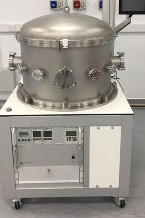
Figure 4. Thermal vacuum chamber
Voltage breakdown phenomena
A subset of RF products that are used in satellite communication systems and space missions, including filters, multiplexers and isolators, can be subjected to high power levels. In vacuum or low-pressure environments, these high-power levels can lead to voltage breakdown phenomena that include corona and multipaction events. A corona event can block or partially block RF signals or RF power transmissions and can ultimately damage critical hardware. To assess corona susceptibility performance, products under development or manufacturing phases are subjected to atmospheric pressure tests under high RF power conditions in a thermal vacuum chamber (TVAC) while monitoring key performance parameters. This testing typically includes cycling the product repeatedly through a critical pressure range often referred to as the Paschen Curve.
A multipaction effect can also render a device useless and degrade the satellite reliability. This event can be triggered in space by a combination of cosmic radiation, high RF power levels, high vacuum levels typical of deep space (e.g., International Space Station orbit height and higher) and gaps between product surfaces that are created within a critical range proportional to the RF frequency used. The type of material used for the product wall constructions can also have a major influence on the susceptibility to multipaction phenomena. Testing for simulated multipaction breakdown in a laboratory requires a sophisticated and expensive test setup, as well as considerable test expertise. It typically comprises the combination of a TVAC, high power amplifier and RF source (for each test frequency band required), plus sophisticated multipaction detection means, including harmonic content monitoring and electron charge detection.
Due to the significant and costly impact of a multipaction event in deep space, multipaction analysis and testing typically requires very large margins of safety. This requires laboratory testing at high-power levels – often four times higher than nominal hardware operating power levels – and leads to very expensive power amplification for laboratory testing which increases significantly at the higher GHz levels (beyond K-band).

Figure 5: Typical multipaction test setup in Dundee test and qualification laboratory
Electromagnetic environments
Electromagnetic waves from the space environment and other on-board electronics can disrupt the operation of electronic devices by causing voltage changes, excessive noise or faults in electronic circuitry. To mitigate these effects, some product classes are designed to incorporate electromagnetic shielding. The effectiveness of this shielding is evaluated during the design and manufacturing phases by exposing the products to artificially induced levels of microwave radiation in an electromagnetic compatibility (EMC) test chamber (Figure 6).
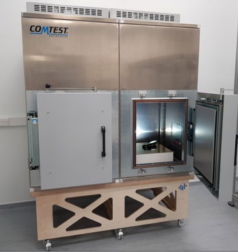
Figure 6. EMC test chamber
Terrestrial environments
Space-bound products and systems may be subjected to a variety of handling, transportation and storage environments over their operational lifetimes. These environments include shock, vibration, temperature, humidity, moisture and corrosive environments. Testing usually includes worst case terrestrial environments and is often performed in the same facilities used for operational testing.
Dundee test facility
Since 2019, Smiths Interconnect has built and commissioned a dedicated, state-of-the-art 300 square meter qualification and test laboratory at their Dundee, Scotland location. This facility represents a significant financial investment and today includes multipaction, corona and high-power thermal vacuum testing from UHF band through to K band, dynamic stress screening including vibration and classical mechanical shock testing to levels approaching 225 g, with SRS mechanical shock to levels of over 5000 g. The EMC test capability, the latest addition, comprises a two-chamber reverberation test system calibrated to 40 GHz. Additionally, investments in microscope imaging and RF VNA testing up to 110 GHz have expanded the site’s specialized test capabilities.
This facility, while normally used for Smiths Interconnect’s projects, is made available to development partners and customers who require independent third-party environmental testing to support Smiths Interconnects process and new product development. This is a key capability that vastly reduces cost and time to complete certain classes of process and product development, especially where refined through iteration to optimize performance and increase design margins.