

RF attenuators are passive electric components that decreases the amplitude level of an incoming signal. Attenuators can be fixed, switched or continuously variable. Adding an attenuator helps control and reduces signal levels in RF/Microwave systems. Below are 8 applications where adding an attenuator is beneficial.
Reduces VSWR mismatch between devices:
Engineers go to great lengths to match the input and output ports of devices such as a couplers, mixers, and amplifiers to a 50 Ohm transmission line. However, a perfect match is often not possible, especially over a wide frequency range. Mismatches can cause unpredictable variations in the response of the circuit resulting in amplitude and phase changes that may distort the signal. Attenuators, in the range of 1 to 3 dB (and sometimes even up to 6 dB) can minimize reflections which would be the source of these problems. Even though some of the desired signal amplitude is lost in the attenuator, the benefits from interstage matching often greatly outweigh the losses in gain which can be compensated for in a later gain stage in the form of increased amplification.
Stabilize cascaded amplifers to prevent oscillation:
In order to be useful, amplifiers need to be unconditionally stable. That is, they should only increase the amplitude of the input signal, not add anything to it. Despite the best of efforts, amplifiers sometimes encounter complex impedances on the input and output ports that can cause the amplifier to enter a condition of instability, usually at specific frequencies. In it’s worse possible manifestation, this could result in uncontrolled oscillation. But even if continuous oscillation does not occur, damped oscillation or “ringing” would play havoc on circuits that depend on critical timing between fast rise-time pulses such as radar and GPS systems. A simple, inexpensive, and industry accepted cure for this problem is to place an attenuator, in the range 1 to 6 dB, at the input and output of the amplifier. This has the effect of improving the match between stages and dampening out any reactive components that might be a source of any instability.
Balance multiple channels:
In many systems it is necessary to balance the amplitude of multiple channels very accurately. Even though a group of amplifiers are purchased from the same source, they can vary in amplitude from unit to unit due to small process variations at the time of manufacture. Attenuators are an inexpensive and highly desirable way to balance these amplifiers to very high accuracy. In addition, these attenuators would provide all the other benefits such as improved matching and stability.
Calibrate or adjust amplifiers gain:
When a precise amount of gain is required for a circuit, it is often almost impossible to obtain an off-the-shelf amplifier that has the exact amount of gain needed. Also, since practically every circuit encounters unexpected gain losses during the manufacture of the final product, in general, it would be prudent to specify an amplifier with slightly more gain than is actually required.
An attenuator can then be used to set the gain precisely to what is required and obtain all the secondary benefits discussed previously like improved matching and stability.
Protect the input to an amplifier (Prevent overload):
Certain electronic instruments like Spectrum Analyzers and Radar Receivers need to be able to operate over a wide range of signal levels on the input. One way to do this would be with a variable gain amplifier in which the gain can be preset for the desired amplification factor. Unfortunately, these types of amplifiers have some side effects that would be detrimental to the desired function of the finished instrument. Therefore, it is common practice to design the instrument so that the system gain is sufficient for even the smallest input signal, then use attenuators to “pad” the input when larger signals are present. These attenuators can be switched in and out either manually or electronically when needed using RF Switches.
Match impedances (Minimum Loss Pad):
Suppose an engineer needed to match the 50 Ohm output of an oscillator to the 150 Ohm input of an amplifier. One way to do that would be with reactive matching or a balun which has essentially almost zero loss. But suppose the engineer needed to pad to output by 10 dB in order to avoid overdriving the amplifier and to isolate the oscillator from changes in impedance to prevent shifting (pulling) of the frequency. A Minimum Loss Pad consisting of only two resistors could do the job in a smaller, more reliable, and less expensive package. Therefore, instead of two separate components, only one component would be needed for both the 10 dB attenuator and the impedance matching device saving the customer board space and increasing reliability. In addition, because the Minimum Loss Pad is a broadband device, only one part number could be used for numerous applications reducing stocking requirements.
Sample a high power signal for test purposes:
There exists many applications in which the output of a high power amplifier needs to be sampled for leveling or test purposes. For example, suppose the output of a 100 watt (+50 dBm) transmitter needs to be monitored using a Spectrum Analyzer. One way the power could be sampled is by using a 20 dB Coupler. This would have only a very small effect on the primary thru signal and provide a reference signal of 1 watt (+20 dBm) for test purposes. But there are a number of problems with this configuration. First, 1 watt is too large to connect directly to the input of a Spectrum Analyzer. Second, when the Spectrum Analyzer is disconnected from the test port it would cause some undesirable effects on the coupler unless a termination were attached to the port. Terminations which are not permanently attached to a port have a habit of getting lost.
A better solution would be to use a 30 dB attenuator permanently attached to the output of the coupler. This would reduce the output level to 1 mW (0 dBm) which is well within the desired measurement range of the Spectrum Analyzer.
A secondary benefit would be realized when the analyzer is disconnected. Since the 30 dB attenuator has high front to back isolation, the test port at the coupler would continue to maintain a good 50 Ohm match to the coupler thus prevent undesirable effects to the thru signal.
Compensate Gain over Temperature (Thermopad®):
It is well known in the industry that uncompensated amplifiers have a problem maintaining constant gain over changes in ambient temperature. These changes can typically be more than 3 dB. Thermopads®, otherwise known as Temperature Variable Attenuators can compensate for gain variations by changing their attenuation in the opposite direction of the amplifier. This has the desired effect of flattening out the gain of the amplifier when it is exposed to differing temperatures. Since TVA’s are conventional passive attenuators at any constant temperature, they also provide all the addition benefits such as improved matching and stability over frequency.
.jpg)
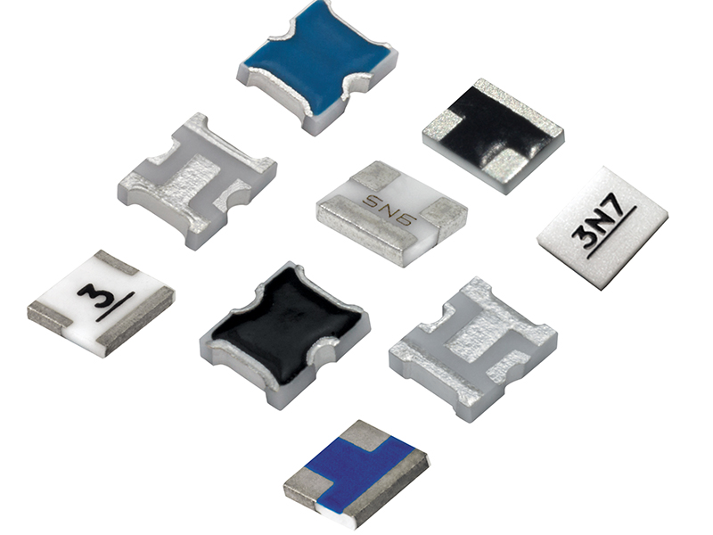
Thermopad® attenuator products are a totally passive, easy to implement solution for gain compensation designed specifically for demanding high reliability applications. Temperature variable attenuators can be used in place of a standard chip attenuator to combine level setting or buffering and temperature compensation in a single chip design. This will reduce component count, increase reliability, and lower costs. Applications include power amplifiers, mixers, MMIC amplifiers, directional couplers and diode detectors.
For addtional support please use the Thermopad® Temperature Shift Reference chart below: